 At Fakuma, Sigma Engineering GmbH from Aachen showcased the newest applications of its Sigmasoft Autonomous Optimization, exhibiting at booth A5-5105. In this new simulation approach, now contained in the Sigmasoft Virtual Molding technology, the user defines a specific objective, e.g. the balanced filling of multiple cavities, and the simulation determines the configuration optimally fulfilling this objective, using just one calculation with a variety of variables. The user compares different configurations based on specific values, significantly shortening the time to find the best result. Consequently, trial-and-error experiments are not just moved from the injection molding machine to the computer but reduced to a minimum, since the software facilitates the user’s decisions regarding geometry or process changes.
In the example at hand, the runner system of a family mold should get optimized to achieve a balanced filling of the different parts. These are differing considerably in volume and wall thickness. Therefore, filling happened to be very unbalanced with the original runner system, leading to a single component affecting the productivity of the entire process.
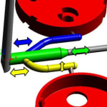
The possibility to execute a virtual DoE (Design of Experiments) is an integral part of the Autonomous Optimization. It was utilized to optimize the design and achieve a balanced filling of all cavities of the aforementioned family mold. Initially, the adjustable geometric parameters were determined (Figure 1). The length of the main sprue’s local increase of thickness, radius of the bottom sprue and the respective starting points of the lateral sprues, where they branch away from the main sprue were specified as degrees of freedom. Additionally, the desired target value was defined. These are minimal differences in filling times of the individual components as well as a low filling pressure.
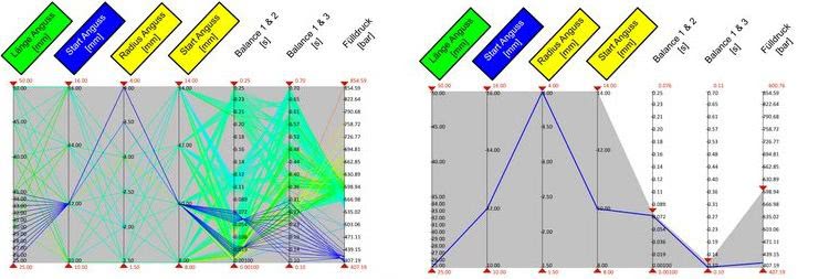
In evaluation, every version is represented by one line, the vertical sliders show degrees of freedom and target values (left). The user can narrow both down via the sliders and thus identify the ideal variant (right)
After calculating all geometry variants with the help of a virtual DoE, they are compared and evaluated regarding the differences in filling times (Figure 2). On the left side, all calculated variants are shown each represented by a colored line. The specific columns are depicting the degrees of freedom and target values, as well as their possible characteristics. Afterwards, the user utilizes the sliders at the columns to limit the target values to the desired values, identifying the optimal variant (Figure 2, right). In this example, the filling pressure should be lower than 600 bar while the maximal difference in filling time for the cavities amounts to 0,1 s. The determined runner design shows a distinct increase in filling balance of the individual cavities (Figure 3). Subsequently, this geometry will be used as basis for more detailed optimizations of mold and process configuration.
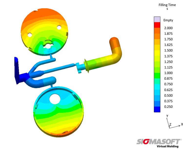
Optimal design with balanced filling and approximately even filling times in all cavities
By means of the virtual DoE, contained in the Sigmasoft Autonomous Optimization, geometrical changes can be checked with very slight effort. At the same time, the influence on defined objectives, e.g. differences in filling times of multiple cavities or filling pressure, can be evaluated. Hereby, users can find the ideal runner design to match their requirements very fast and safely, even while combining very diverse parts in their molds.
Source: Sigma Engineering GmbH


